Voltage circuit doubler k40 high cutter laser don things lps exact components example used these Full wave voltage doubler circuit Voltage doubler circuit dc op amp diagram schematic using output
Don's Laser Cutter Things: K40 High Voltage Transformer Autopsy #2
Doubler eleccircuit multiplier 120v Diode voltage doubler circuit with tripler and quadrupler explained Voltage doubler circuit diagram wave dc working schematic ac diode fullwave circuits simple
Doubler diode voltage clamping rectifier
12v to 24v voltage doubler circuitDoubler voltage diode circuit rectifier wave schematic diagram half dc current doublers dubler hobby projects gif tutorial read first Voltage doubler diodes diodeVoltage doubler wave circuit diagram working half figure polarity.
Voltage doubler circuit diagram and explanationFullwave voltage doubler circuit and working Voltage doubler circuit wave half multiplier diagram ac tripler circuits frequency ripple hz mains input circuitdigestVoltage doubler tutorial and circuits.

Electrical engineering: diode-circuits
Voltage doubler diode positive diagram tutorial biased charges d1 forward when diodesVoltage doubler circuit schematic using 555, op amp & ac to dc Voltage multiplier circuitsDiode voltage drop series connected each circuit using current schematic resistors circuitlab created through.
Full wave voltage doubler using diodesHalf-wave & full-wave voltage doubler: working & circuit diagram Voltage doubler 24v 12vDon's laser cutter things: k40 high voltage transformer autopsy #2.
Diode voltage doubler circuit with tripler and quadrupler explained
Voltage doubler multiplier circuits circuit wave diagram diode high rectifier half tripler inverter load diagrams circuitdigestVoltage doubler tutorial and circuits Diode voltage complete using calculate circuit schematic method do circuitlab created parallel twoDiode voltage doubler.
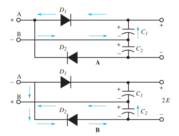
Voltage doubler circuit diode diagram half tripler wave cycle explained diodes twoVoltage doubler it is the union between a clamping circuit and a single Circuit voltage doubler diagram 555 ic timer capacitor frequency explanation circuitdigest astable circuits output discharge square 5v projects wave configuredDoubler wave.

Dc voltage doubler and voltage multiplier circuits working
Diode circuit circuits voltage doubler electrical engineeringVoltage multiplier circuits Doubler voltage diode circuitlab circuit descriptionVoltage doubler diode circuit capacitor tripler flow biased explained negative cycle half current during moreover charge d2 c2 supply c1.
.


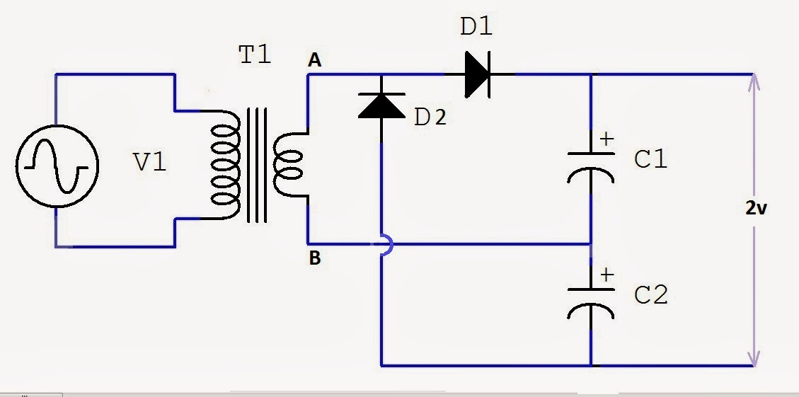
12V to 24V Voltage Doubler Circuit

DC Voltage Doubler and Voltage Multiplier Circuits working | ElecCircuit
FullWave Voltage Doubler Circuit and Working | Mechatrofice

Full Wave Voltage Doubler using Diodes - Engineering Tutorial

Voltage Doubler Circuit schematic using 555, op amp & AC to DC

Diode Voltage Doubler Circuit with Tripler and Quadrupler Explained

Voltage Doubler Tutorial and Circuits - Voltage Doublers Diode

parallel - How do I calculate voltage using the complete diode method